
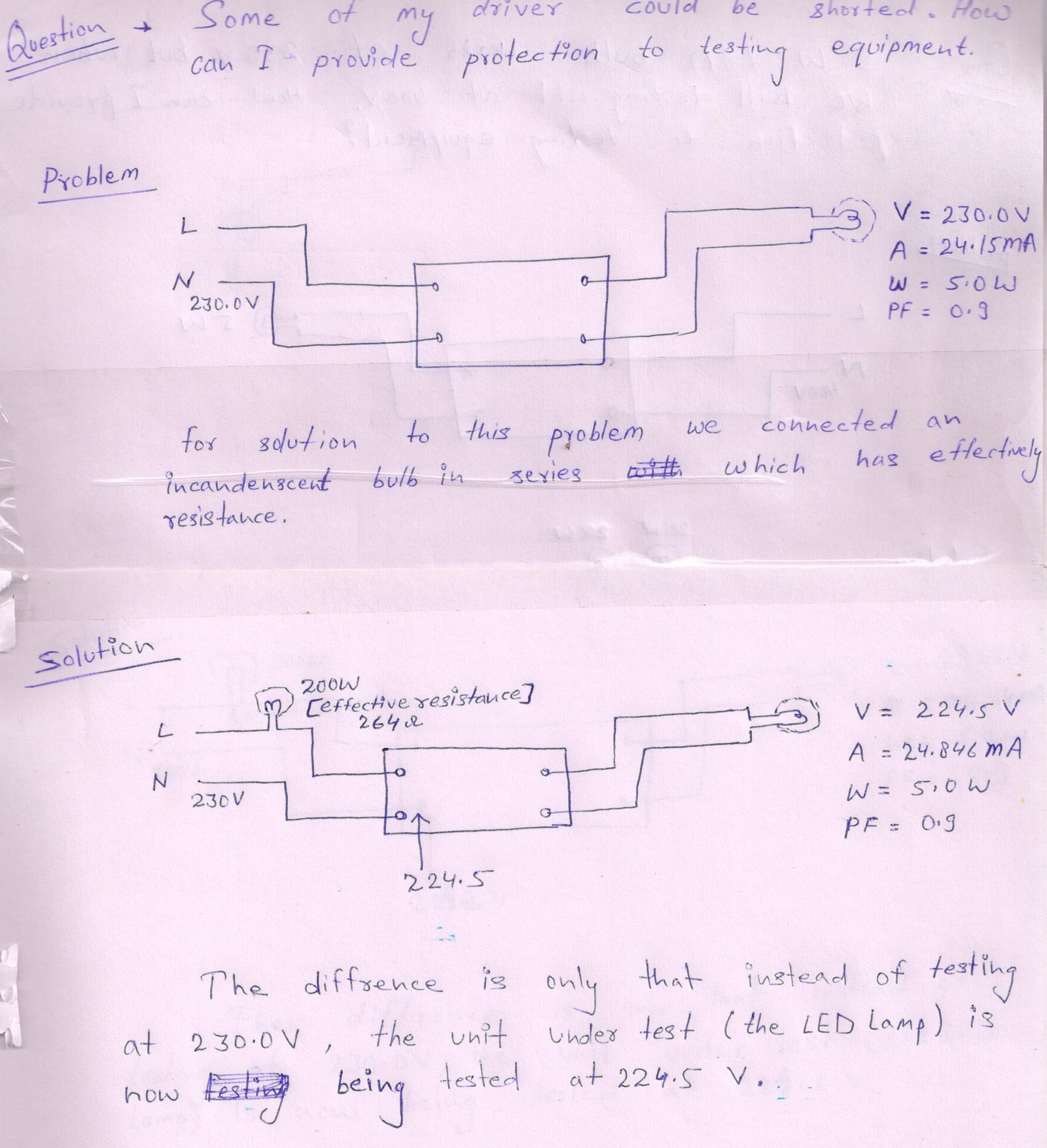
When testing a large number of LED drivers or LED bulbs, some devices under test (DUTs) may have an internal short circuit. A shorted DUT can draw excessive current and may damage the electronic components of the testing equipment.
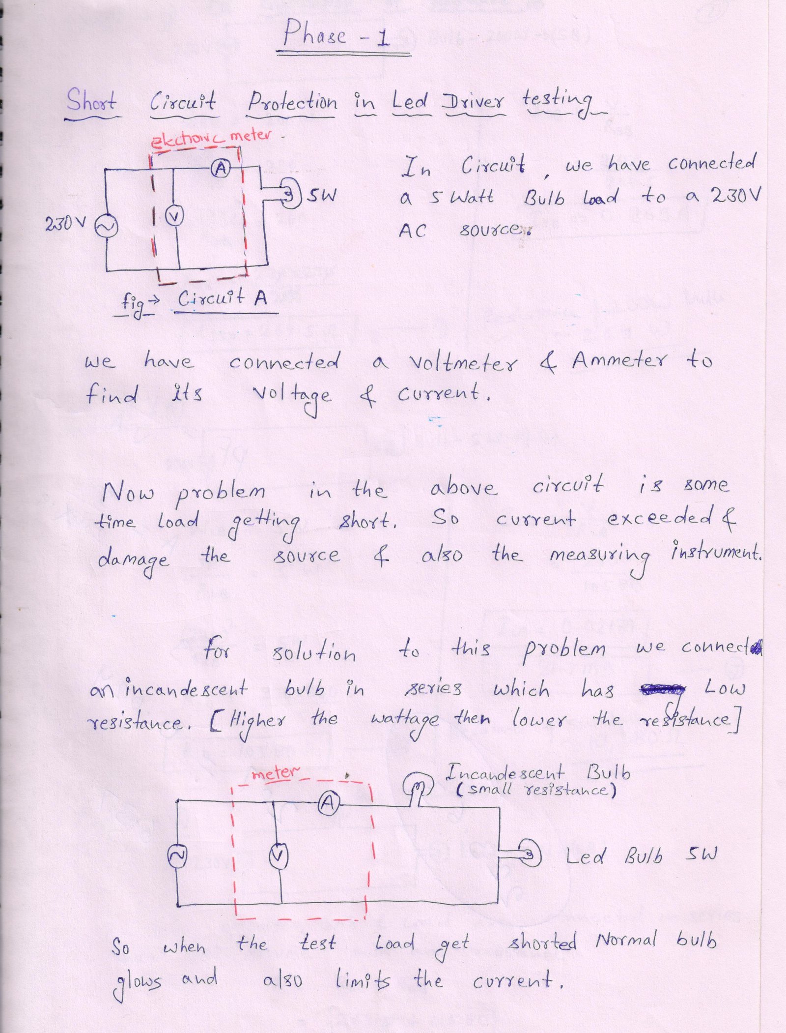
A simple and effective method of protecting the testing equipment is to use a series incandescent bulb as a current limiter.
1. Testing a 5 W LED Bulb
The power strip is used to supply power to the testing equipment through the black power cord. The red and black wires provide the test input power to the LED bulb.
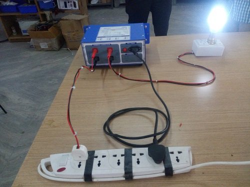
Figure 1: Connection diagram of a 5 W LED bulb with testing equipment
The LED bulb is connected to the testing equipment through a protection circuit. If the LED bulb is internally shorted, the protection circuit limits the fault current and protects the testing equipment.
2. Short Circuit Protection Using an Incandescent Bulb
For simple and economical protection, a 100 W incandescent bulb can be connected in series with the LED bulb under test.
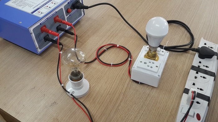
Figure 2: Connection diagram of an incandescent bulb with testing equipment
The incandescent bulb acts as a current limiter during a short-circuit condition.
How does it work?
Under normal operating conditions, the LED bulb operates normally and the series incandescent bulb remains dim or may not glow significantly.
If the LED bulb is short-circuited, the current through the circuit increases. The incandescent bulb then lights up brightly and limits the current flowing through the testing equipment.
This provides two benefits:
- Protects the testing equipment from excessive fault current
- Provides a visual indication of a short circuit
3. Incandescent Bulb Series Connection
The following image shows the correct series connection of the incandescent bulb.
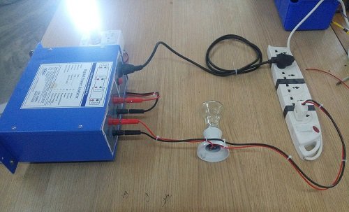
Figure 3: Incandescent bulb series connection
The incandescent bulb must be connected in series, not in parallel, with the load being tested.
4. Short Circuit Test
To demonstrate the protection, the LED load can be intentionally shorted using a wire.
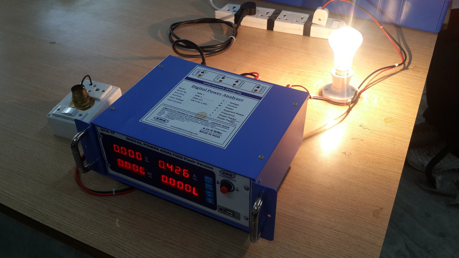
Figure 4: Short-circuit test
When the load is shorted, the incandescent bulb lights up brightly. This indicates a short-circuit condition to the operator while limiting the fault current.
Technical Explanation
The series incandescent bulb works as a simple current-limiting device.
For example, consider a 100 W incandescent bulb rated for 230 V:
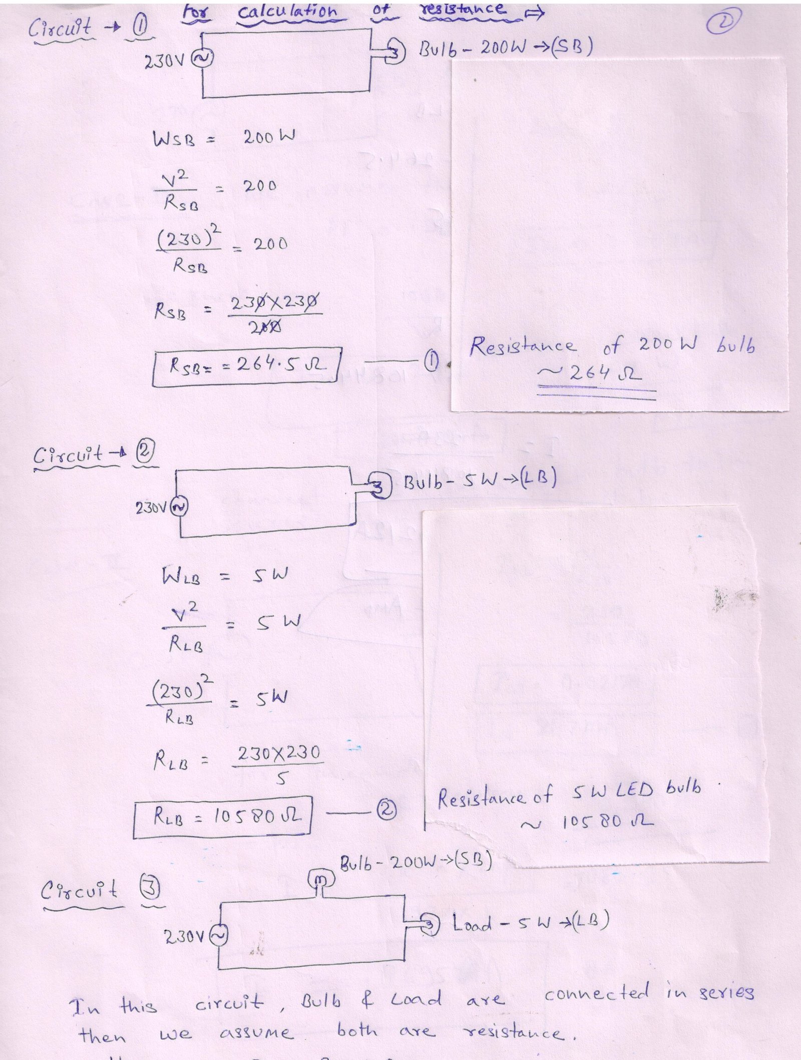
Therefore, when a short circuit occurs, the incandescent filament heats up and its resistance increases significantly, limiting the current flowing through the test equipment.
Note: The resistance of an incandescent bulb is much lower when the filament is cold and increases substantially as the filament heats up.
LED Bulb Testing at Higher Voltage
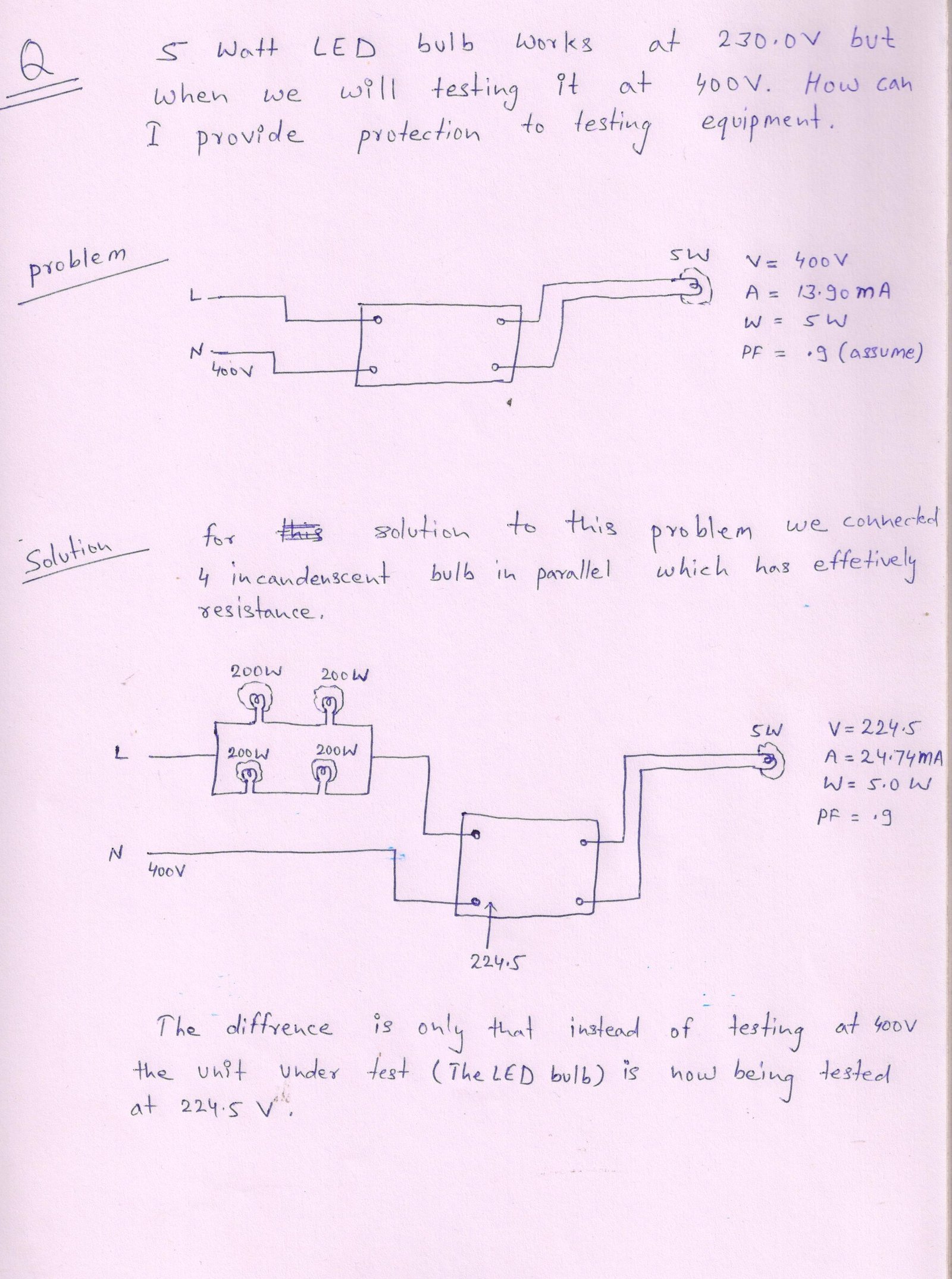
The same protection concept can also be applied when testing LED bulbs at higher voltages, such as 400 V, but the protection components must be selected according to the test voltage, maximum current, DUT power, and the maximum allowable current of the testing equipment.
For higher-voltage testing, additional protection such as:
- Fast-acting fuses
- MCBs
- Relays/contactors
- Electronic current limiting
- Over-current detection
- Automatic output shutdown
may be incorporated into the tester.
Conclusion
A series incandescent bulb provides a simple, low-cost method of protecting LED driver testing equipment against short-circuit DUTs. The bulb limits the fault current and provides a clear visual indication when a short circuit occurs.
For professional automated testing equipment, however, an electronic current-limiting and over-current protection circuit can provide more precise and repeatable protection than an incandescent bulb.